Language: 


THE EQUIPMENT FOR SUPERSONIC PLASMA SPRAYING OF PLAZER
|
||||||||||||||||||||||||||||||||||||||||||||||||||||||||||||||||||||||||||||||||
|
Parameters |
Types of installations |
||
|
PLAZER 50-PL |
PLAZER 80-PL-S |
PLAZER 180-PL-S |
|
|
Plasma forming gas |
Air + propane or methane (up to |
||
|
Plasma temperature, K |
|
|
|
|
Plasma jet velocity, m/s |
|
|
|
|
Spraying particles velocity, m/s |
|
|
|
|
Spraying rate, kg/h — metal powders — ceramic powders (oxides) |
up to 15 up to 8 |
up to 25 up to 15 |
up to 50 up to 25 |
|
Electric power , kilowatt |
|
|
|
|
Spraying material use factor |
up to 0,7 |
up to 0,75 |
up to |
Specifications of the installation PLAZER 180-PL-S
|
Parameter |
Value |
|
Three phase alternative current supply-line operation voltage at 50 Hz frequency, V |
380 (-10... +5) |
|
Open-circuit voltage, V |
540 |
|
Duty factor, DF, % |
100 |
|
Arc operating voltage, В |
200 — 450 |
|
Arc operating current, А |
150 — 350 |
|
Working pressure of mixture, MPa |
0,15 — 0,7 |
|
Circuit air pressure, MPa |
0,8 — 2,5 |
|
Plasma forming air consumption, nm3/h |
10 — 35 |
|
Circuit pressure of plasma forming combustible gas (propane-butane), MPa |
0,6 — 0,9 |
|
Plasma forming combustible gas consumption (propane-butane), nm3/h: |
0,0 — 3,0 |
|
Carrier gas consumption (air, argon), nm3/h |
0,5 — 2 |
|
Cooling water pressure, MPa |
0,3 |
|
Cooling water consumption, m3/h |
1,0 |
|
Feeder rotary speed, rpm |
0 — 80 |
|
One feeder capacity, dm3 |
5 |
|
Distortion tolerance of powder material feeding from the feeder, % |
± 5 |
|
Grains size of powder materials for spraying, micron: No less No more |
20 160 |
|
Maximal spraying rate, kg/h: Ceramic powders Metal powders |
|
|
Powder use factor, no less |
0,7 |
|
Electric power consumption, kVA, no more |
|
The given equipment has block-modular configuration and includes following main units: plasmatron unit, cables and connecting hoses package, powder feeders system, control system, gas preparation unit, specialized power source.
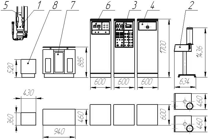
External view and overall dimensions of the installation PLAZER 180-PL-S:
1- plasmatron;
Plasmatron unit includes supersonic plasmatron, collector unit, device for sprayed powder feeding into the channel of (under the cut) nozzle, mounting unit with workpeace cooling device and designated for conversion of electric energy into thermal as plasma jet, where the sprayed powder material is heated and accelerated.
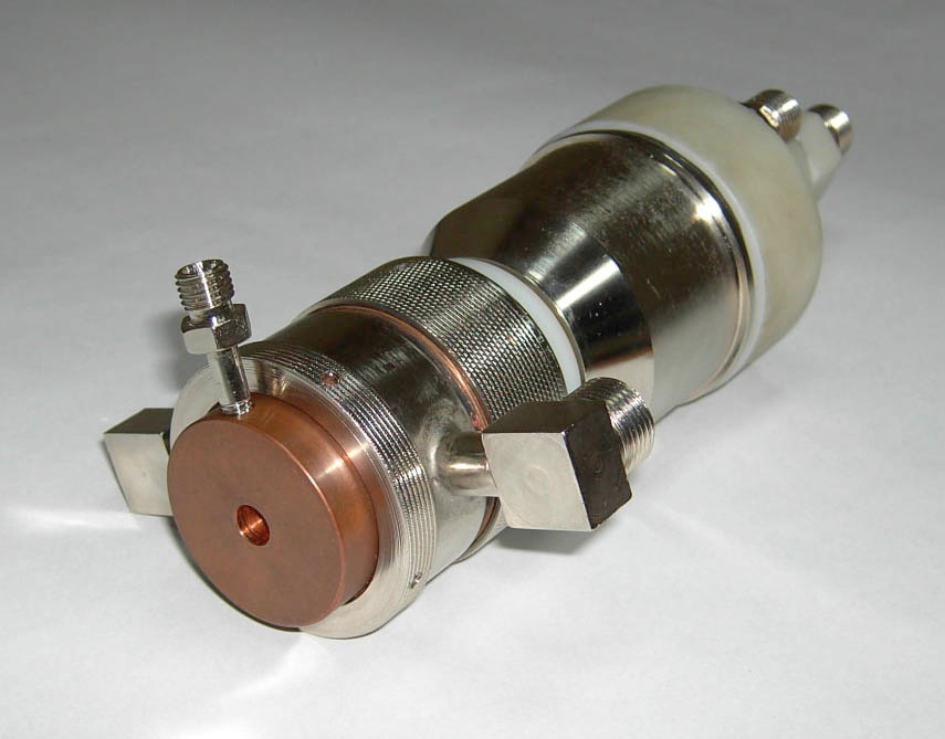
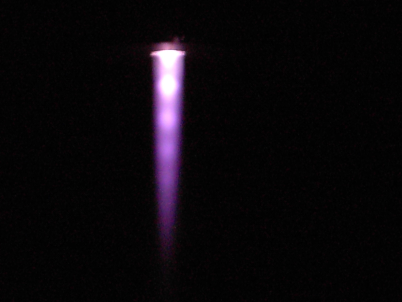
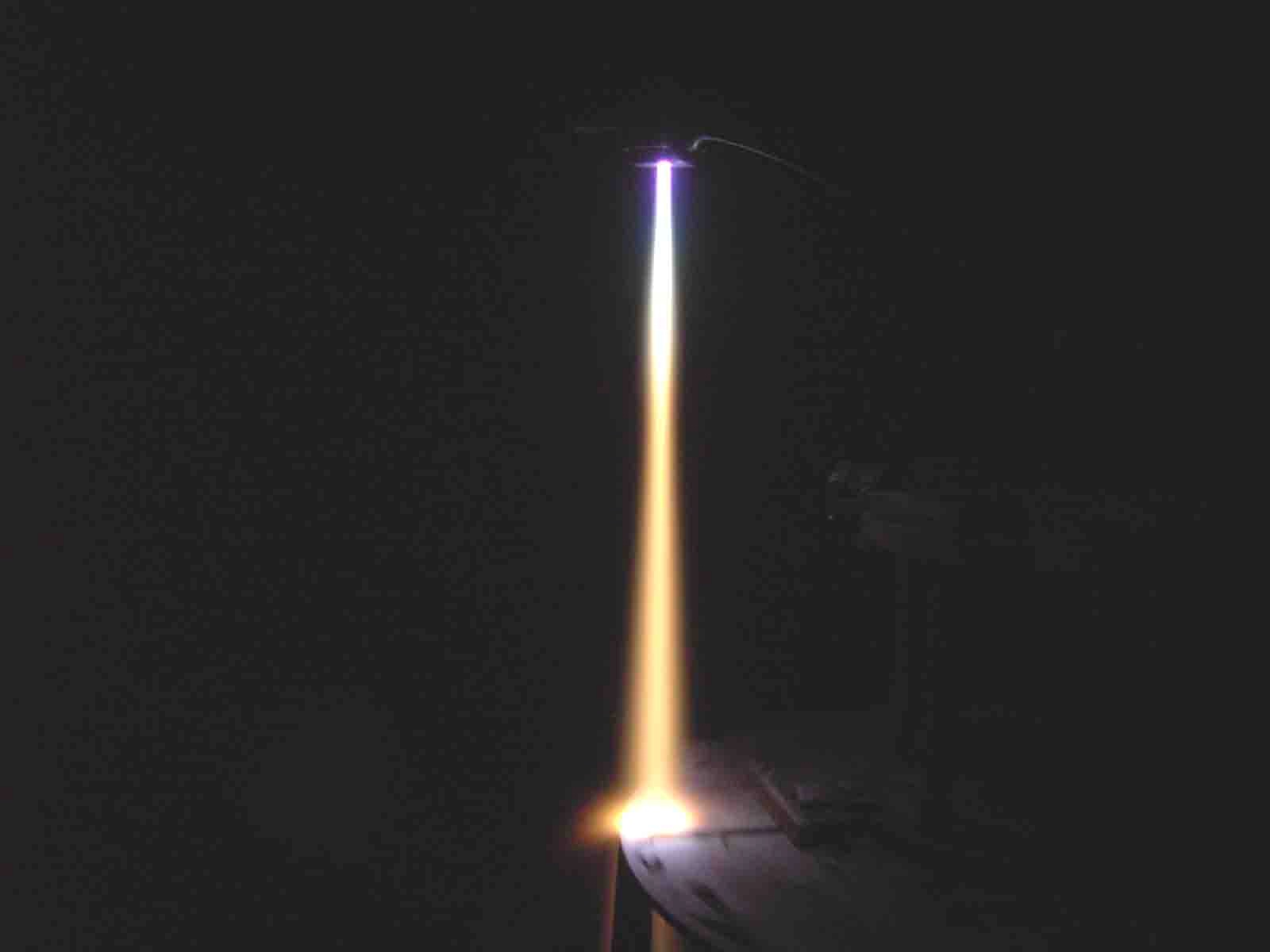
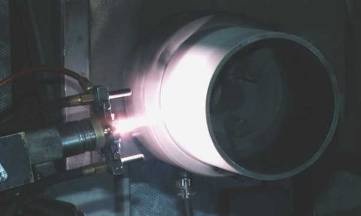
а — plasmatron for supersonic spraying capacity 100 kW, b — underexpanded supersonic plasma jet 1,5 Mach, c — heating before melting and accelerating up to
Plasmatron is made based on three-electrode chart and include water cooling film cathode with hafnium active insert, neutral single interelectrode insert and exit nozzle-anode. Temperature area safely fixes average arc length between front cathode and hollow anode. Arc channel is designed in such a way that downstream along plasma flow in the anode nozzle channel (throat) the thickness boundary layer is increased. At overcritical pressure difference, (in the arc channel relatively to atmosphere pressure) at a distance of 0,5 of it's diameter up to a nozzle cut an artificial critical section is formed due to boundary layer "falloff". Under this mode, plasmatron generates underexpanded supersonic plasma jet with 1,3 — 1,5 Mach number. Spraying powder can be fed either to plasmatron nozzle cut or into the channel in the critical section area.
Supersonic plasmatron of PLAZER 180-PL-S installation has a number of design features which provide:
1. Record high, for plasma spraying and gas-thermal spraying, efficiency (25 kg of spraying material per hour and above);
2. Usability and serviceability of maintenance, reliability and maintainability;
3. Efficiency coefficient
4. High extent of arc length stabilization;
5. Wide control range of bulk enthalpy in plasma jet;
6. Decrease of arc parameters' fluctuation (regular and irregular) and, accordingly, of plasma jet;
7. Suppression of all around plasma jet turbulence and, thus, also the spraying particles dispersion level;
8. Reproducibility of all plasma jet parameters (velocity and enthalpy, their fluctuation values and averaged values, across the jet profiles and longitudinal allocation), within preset and guaranteed time of plasmatrom operation.
At spraying using such supersonic plasmatron, even in the absence of careful process optimization, a considerable improvement of all coatings' qualitative indexes is observed. Porosity reduces from 8 ?12% up to
Plasmatron is designated for mechanical spraying and could be mounted (fixed) on the support of any machine or other mechanical device. The chamber with combined extract and input ventilation should be chosen depending on sizes and shapes of sprayed product, mechanisms for their fixing and moving.
Control system is intended for control of plasma equipment set availability, spraying processes start and cutoff, visual observation and mode parameters adjustment, as well as for feeding to plasmatron of electric power, plasma forming gases and cooling agent.
Control system comprises of following modules:
At reduction of fluid flow or temperature relatively to initial value by 10%, the warning signal of cooling system is displayed. There is an ability to cut-off of this signal by the operator in case if the dynamic of pressure dropping in supply line has no catastrophic nature. At that the current value of the water flow is fixed, which in the future is subject of the same comparison.
The choice of measuring unit of the gas flow carries out by the user from the list: l / min, m3/hour. Gas flow is calibrated against each gas type, with ability to save the calibrating adjustments preservation. Activation ability and ability of dropping of each channel is provided, both during start stage preparation, and in the course of measurement. Evolution of costs for each of the activated channels displayed graphically with the ability to change the scale on both axes. Next to the graph for each of the activated channels the gas type is displayed as well as setting and the current flow rate. If the adjustment and the rate measured value difference exceeds the limit determined by the operator, warning signal is displayed.
Gas preparation unit is designated for feeding and measurement of propane-butane flow rate in plasma forming mixture. Gas preparation unit is intended for preparation of definite proportion air-gas mixture applied as plasma forming gas, and its delivering to supersonic plasmatron. Gas preparation unit contains assembly units and feed, regulation and fire gas (propane-butane) control devices, plasma forming gas mixer. At the front panel of gas preparation unit the rotameter is placed.
Ventilation of gas preparation unit is designed by natural way. Assembly units and fire gas (propane-butane) control and regulation devices connected using pipe line fittings are mounted inside the unit. The mixer is designated for the formation of uniform gas-air mixture. Pressure gauges, pressure control valves, flow-regulating valves and electronic flow meter are placed inside the gas preparation unit.
Pneumatic control valve provides access of propane-butane to the proportional pressure valve, which regulates plasma forming gas supply depending on control pressure. Gas flow is controlled with rotameter and maintained automatically depending on plasma forming air flow rate in such way that preset proportion is still constant (permanent). Fire gas is fed only at condition that electric arc is burning and at the presence of controlling pressure of plasma forming air. Plasma forming mixture is prepared in gas preparation unit mixer, where the air is fed from the control cabinet. Appropriate proportion is prepared using propane-butane flow regulator, which receives air controlling pressure from the control cabinet.
Powder feeders system consists of two powder feeders (dosing devices) and designated for feeding and dosing of one or two heterogeneous powder materials using manual or automatic modes according predetermined program.
Specialized power source is intended for power supply of direct current plasmatron. It provides smooth cut-in/cut-off of the pilot arc, gradual rising of operating current along basic circuit from minimum value to preset value at the start, operating arc preset current stabilization during operation, with accuracy no less than 2,5%, ability to change operating current in the during operation, current and load voltage control. The embodiment involves three units: in the first unit comprises automatic circuit breaker, power solenoid starter, power thyristors block, control system printed circuit assemblies, regulation and protection, auxiliary units panel (of pilot arc), control and protection devices, in the second unit the power transformer is located, in the third- the output supply choke( reactor).
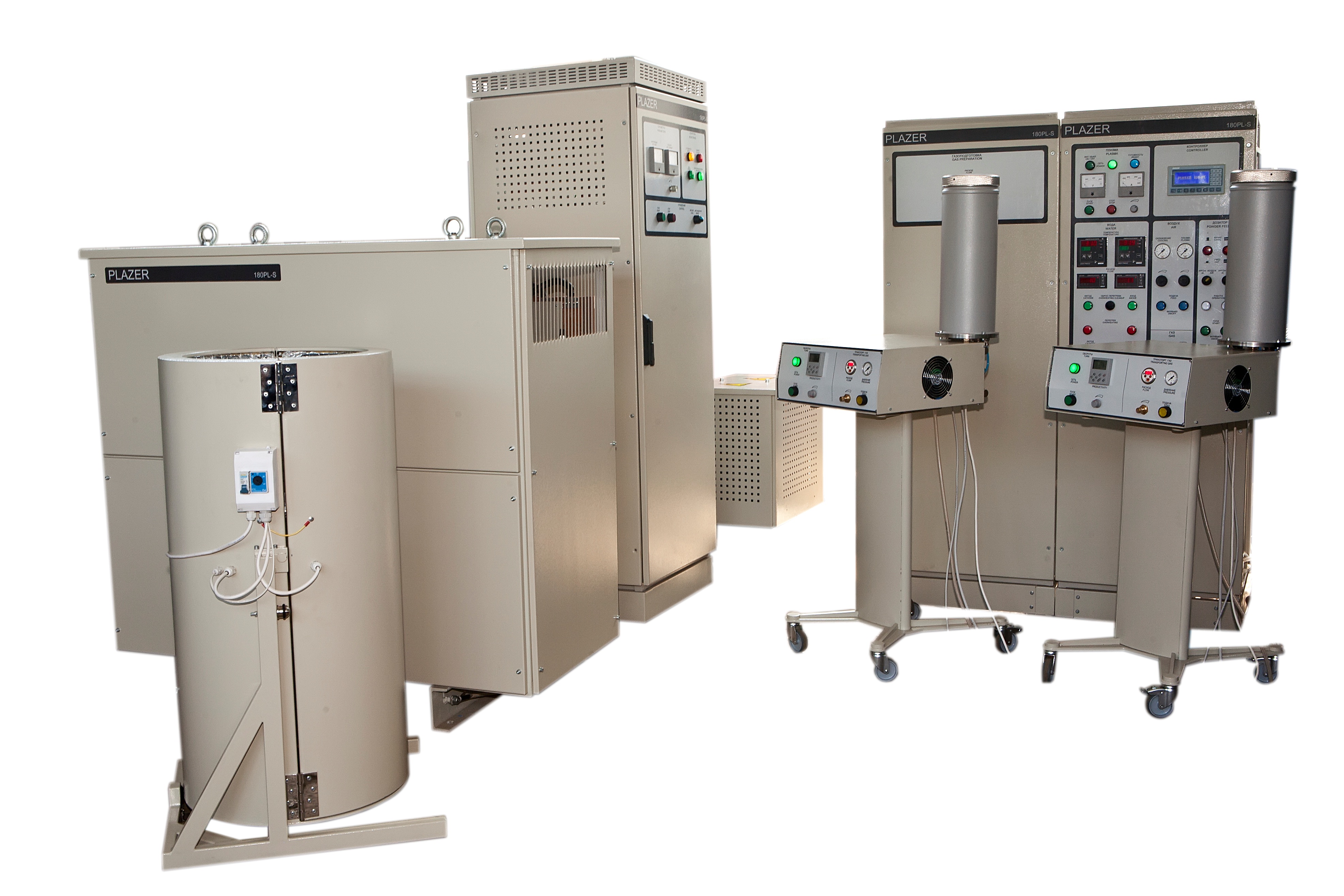
External view of the installation PLAZER 180-PL-S.
Powder feeders system is designated for powders supply to the plasmatron. It includes two feeders, consisting of the following main units: turnover air-proof tank with transparent cover and disc dosing mechanism, asynchronous motor with с variable-frequency electric drive and reduction gear, carrier gas system, rotation gear with locking device.
The powder feeder includes the following major components: the bunker (with the possibility of tripping) with disc dosing mechanism; induction motor with frequency vary-drive and reduction gear, gas carrier system (providing supply of powder into supersonic jet), rotation gear with locking device.
The total capacity of two feeders for supersonic plasma spraying installation — not less than 10 liters of powder.The accuracy of powder feeding is not less than 5%.
Rotation speed of the feeder's dosing device is displayed on the controller display (industrial computer) and adjusted manually. Transmitting powder particle size:
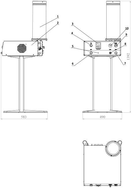
Powder feeder (dosing device) of the installation PLAZER 180-PL-S.
1- bunker; 2- housing; 3- discharge sensor (gas consumption); 4- lamp (light) "Circuit"; 5- handle for rotation speed control; 6- button " START"; 7 button "SUPPLY"; 8- capacity regulator; 9- manometer; 10- flowmeter.
The Process of Supersonic Plasma Spraying of coatings using equipment PLAZER®
 |
The list of key parts for supersonic plasma spraying of coatings using equipment PLAZER® contains various machinery and toolware. These are the parts of compressors and hot section of airplane and ship gas-turbine engines, aircrafts, compressors, rotor wheels, turbine shafts, plunger pistons, pillars, various pump piston, drill holes bars, hydraulic and power equipment components, papermaking machine drying cylinders, marine diesel shafts and other shipboard equipment components, chemical industry equipment parts, railroad equipment large-dimension components (axles, crankshafts, locomotive connecting-rods and cylinder liners) etc.