Language: 


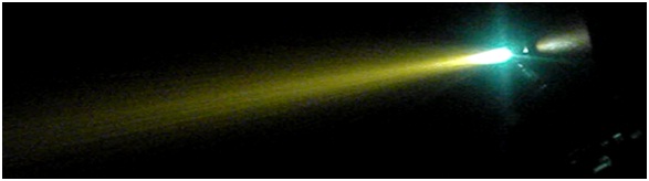
The installation for supersonic electric arc spraying PLAZER15-SADesignation of the installation (unit) The installation is designed for spraying of wear-and corrosion-resistant and special coatings, reclamation of worn-parts of installation s using twin-wire electric-arc spraying in supersonic jet of hot combustion products of hydrocarbon gas with air of conductive materials in the form of wire (cored wire) diameter The installation provides realization of supersonic spraying mode without using of expensive and scarce gases. Compressed air is used as working gas with a small amount of flammable gas of propane or methane — 5%. Air flow for supersonic arc spraying (up to Arc spraying process using given installation generates supersonic jet of high-enthalpy gases, diffusing molten metal of wires and transporting sprayed metal to the product. The installation provides convergence of sprayed wires, formation of the supersonic jet of high-enthalpy combustion products, diffusing molten metal of wires and transporting sprayed metal to the product (Fig. 1). Electric arc burning between the two wires (side and central), melts these wires. Supersonic jet of hot neutral gases at the outlet of the nozzle forms a supersonic jet at a speed more than 1500 m / s at 2200 K, directed to the area of the arc, which melts the wire, diffuses the flux into small droplets and accelerates to a speed of 200 — 500 m/s and above.
Fig. 1. External view of the supersonic jet in the process of twin —wire supersonic electric-arc spraying. The advantage of the process, which is realized using given installation , is reducing of the opening angle of the two-phase metal-gas flow due to the laminarization supersonic flow. This strongly reduces velocity and temperature dispersion of the central and peripheral sprayed particles. The transition to supersonic velocity of the high-temperature jet leads to the high efficiency of the spray particles disperse and reduce the intensity of the heat. Increasing the speed of the particles of sprayed material at the moment of impact with the base in 3 — 4 times higher than traditional subsonic electric arc spraying, provides rising of their kinetic energy in 9 — 16 times, which leads quantum leap of all service properties of sprayed coatings. In general, the twin-wire supersonic arc spraying process, realizing using given installation , compared to traditional electric arc spraying at the subsonic modes of the high-temperature jet, provides reducing oxidation of the sprayed material and burnout of alloying elements, increasing the speed of the sprayed material particles up to Completeness of the installation
Basic technical specifications
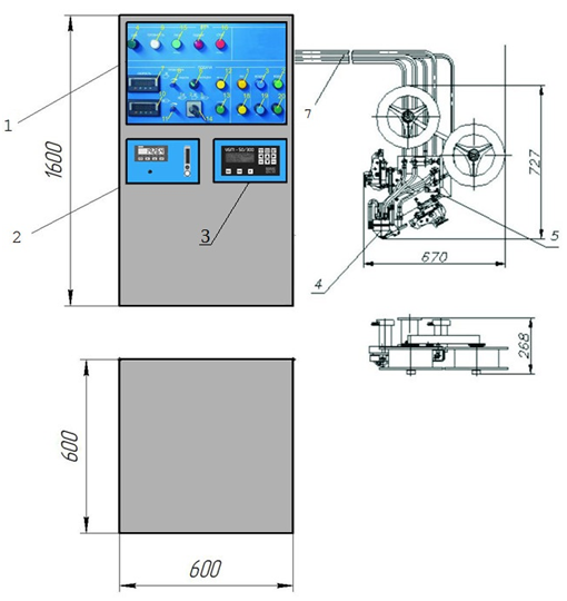
General description of the supersonic electric-arc spraying installation PLAZER15-SA The supersonic electric-arc spraying installation has block-modular design. Control system, electric power source, cooling control module of the supersonic metal spraying gun and gas preparation unit is assembled in on-floor cabinet, twin-wire feeding system of sprayed material is mounted on auxiliary technological equipment (manipulator), depending on the sprayed part type.
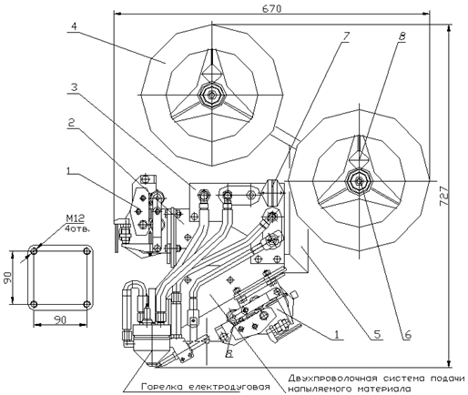
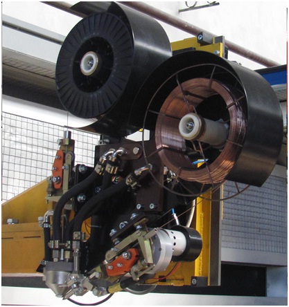
General view and dimensions of the supersonic electric-arc spraying installation . Structure and function of main units of the supersonic electric-arc spraying installation The unit of supersonic electric-arc metal spraying gun The unit of supersonic electric-arc metal spraying gun combines twin-wire feeding system of sprayed material (hereafter — the feeding system) and the electric-arc supersonic head (hereafter — the head). The unit of supersonic electric-arc metal spraying gun is connected with the control system (control console) using the set of communications (cable and hose package). а
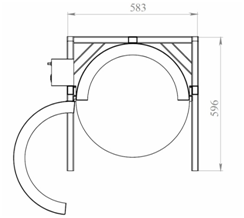
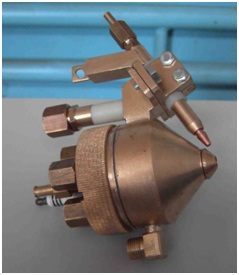
b External view drawing and photo of the supersonic electric-arc metal spraying gun. The body (frame) 2 of the unit of supersonic electric-arc metal spraying gun provides fixing of two gear-motor drives 1 the supersonic head is connected to the bottom of the body (frame). Insulator 3 is designated for placement of connecting pieces of the hoses of gas mixture supply, inlet and outlet of the cooling water and electric cables to the torch. Two wires feeding mechanisms 1 with four replacement rollers 8, two bobbins 4 with sprayed wire and partial braking mechanism 6 are placed on the supporting arm 5. Four tap holes for fixing of the spraying unit to the displacement mechanism are placed on the supporting arm 5. Bobbins 4 are mounted on the axis of braking mechanism and fixed using tap screws 8. Spraying wire must be loaded into wire feeders 1 and then fed into the central and side torch nozzles to touchdown. Replacement feeding rollers 8 are installed from the set of spare parts depending on the spraying wire diameter. The cooling air is supplied for cooling the drive of wire feeding. The supersonic electric-arc head is a device, which provides convergence of two sprayed wires, providing generating of the supersonic jet of high-enthalpy combustion products, diffusing molten metal of wires and transporting droplets of sprayed metal to the product.
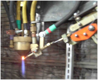
Supersonic electric-arc head: а- external view without cable and hose package ; b — external view at arc ignition The supersonic electric-arc head includes following main units, which fulfill following functions: — the body (frame) operates as combustion chamber; — cathode unit provides current leading and axial direction of the central wire, formation of the gas-air mixture flow in the combustion chamber and fixing the plug, igniting gas-air mixture; — side nozzle provides current leading and direction of the side wire motion; coupling nut; — fixing unit, provides fixing of the cathode unit to the bogy (frame). Cooling of the combustion chamber and the cathode unit carries out using water supplied from the main or independent cooling unit. At supply of high voltage to the spark plug between its electrodes generates a spark, igniting the fuel mixture. Further combustion occurs automatically. Agitation and burning of the arc, melting wires, carries out when the source of power supply and mechanisms of wire feeding with formation of high-supersonic flow are switched-on. The control system The control system is designated to control the operation modes of the installation.
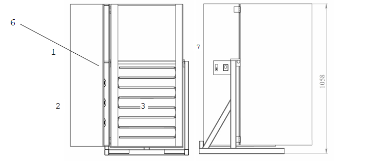
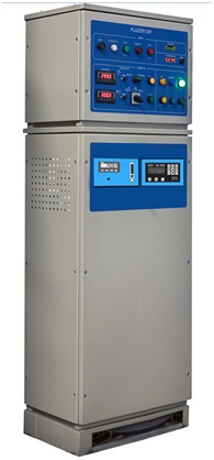
External view of the cabinet of the control system. The control console has block-modular configuration. The control system functions are: — control of operation of the side and central wire feed drives — control of supply of air, water and fuel gas to the electric arc torch; — ignition of the electric arc torch; — indication of conditions and parameters of the installation .
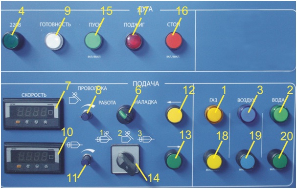
Front panel of the control system: 1. indicator of switching on of the valve for feeding the gas mixture to the torch; 2. indicator of water supply to the torch cooling system; 3. indicator of air supply to air lines; 4. indicator of the presence of voltage in the power mains (~220 V); 5. automatic mains switch, placed of the right inner wall of the control console; 6. mode selection switch ("operation-adjustment"); 7. multimeter for measuring wire feed speed from the side drive; 8. potentiometer for regulation of wire feed speed from the side drive; 9. indicator "Ready" showing readiness of the water and air supply lines for starting the installation ; 10. multimeter for measuring wire feed speed from the central drive; 11. potentiometer for regulation of wire feed speed from the central drive; 12. button for the wire forward feeding by the drives in manual mode; 13. button for the wire reversing feeding by the drives in manual mode 14. select switch for modes of operation of wire feed mechanisms:
15. button "Start" to switch on the installation in automatic mode (position "1" of select switch 14) ; 16. button "Stop" to switch off operation of the installation in automatic mode (position "1" of select switch 14) ; 17. button to switch on high voltage to ignite air-gas mixture in the electric arc torch; 18. button (push-to-lock) to switch on the gas feed valve in the gas preparation unit; 19. button (push-to-lock) to switch on the valve to supply air to air lines of the installation ; 20. button (push-to-lock) to switch on the valve to supply water to cooling system of the electric arc torch; Gas preparation unit. Gas preparation unit is designed to supply fuel gas and compressed air, formation in required proportion of the air-gas mixture and supply it to the electric arc torch. Gas preparation unit is installed inside the control console cabinet
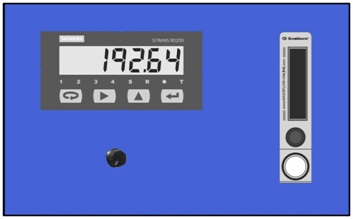
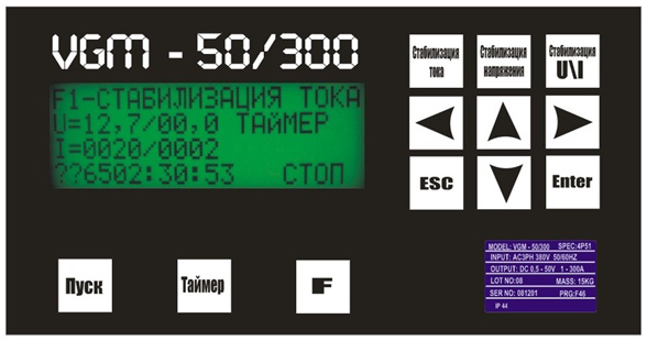
Front panel of the gas preparation unit: — digital indicator of air consumption — potentiometer for air consumption regulation — electronic rotameter for regulation fuel gas flow rate Water cooling control module of the supersonic metal spraying gun provides following functions: — actuation of the cooling water supply into the cooling system of the metal spraying gun; — control of the cooling water flow through the metal spraying gun; — deactivation of voltage supply for wires when the cooling water supply into the system of metal spraying gun is stopped or when the water level is lower than determined level. Cooling control module of the supersonic metal spraying gun includes following components: — electromagnetic valve for water supply actuation — electron relay for the water flow control — filter for purification of water, supplied to the cooling system of electric arc metal spraying gun. — pressure relay, providing operation of the cooling system in safe mode. — manometer gage for visual control of pressure of water supplied for cooling. Specialized power source Specialized power source includes power-supply unit, reactor block, control consol, keyboard display. Power source converses AC three-phases mains voltage 380V into constant output voltage from 0,3 up to 50V. The source functionally consists of a low-frequency three-phase rectifier, smoothing filter, inverter, transformer, output high-frequency rectifier and LC filter.. Mains voltage comes to uncontrolled three-phase rectifier, from which the constant voltage is supplied for power supply of inverter through the Indication panel of the specialized power source is placed on the front section of the source cabinet and includes: indication panel, liquid crystal display and keyboard. Control consol of the liquid crystal display provides setting, stabilization and control of operating voltage for the arc of supersonic electric-arc head.
Control console of the specialized power source. Cables and connecting hoses for gas and water (cable-hose package) The set of cables and connecting hoses (cable-hose package) provides supply of electric power, cooling water and gas mixture to the unit of supersonic metal spraying gun. Includes: the hose of gas-air mixture, hoses for water supply and drain, wire for power supply of ignition spark plug. The length of the cable-hose package from the consol of the system up to the unit of supersonic metal spraying gun — about 7 m. Spare parts and tools
Operation manual Operation manual (guidance on main working practices and servicing of the installation ) includes the following sections: description of the installation operation, intended use of the installation , procedure for safety measures, order assembling and preparation to the operation, order of work control, regulation and adjusting, troubleshooting, maintenance operation, the list of spare parts, tools and accessories. Given operation manual also includes applications: hook-up diagram, connection diagram of the installation , pneumatic-hydraulic circuit. Operation manual is provided in English and Russian.
|